Voltage Divider Calculator
Voltage Dividers
A voltage divider is an electrical circuit consisting of two or more resistors connected in series, used to divide a voltage into smaller, proportionate voltages. The basic principle behind a voltage divider is Ohm's law, which states that the voltage (V) across a resistor is directly proportional to the current (I) flowing through it and the resistance (R) of the resistor, i.e., V = I * R.
Voltage dividers are particularly useful in applications where specific voltage ratios are required, such as sensors and analog signal processing, while also helping to distribute power dissipation more evenly across resistors. However, voltage dividers may not be suitable for high-precision or high-power applications, where other voltage regulation methods may be more appropriate.
The formula to derive the desired output voltage (Vout) in a voltage divider circuit is given by:
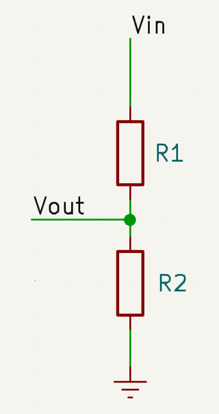
Vout = Vin * ( R2 / ( R1 + R2 ))
Where:
Vin is the input voltage.
Vout is the desired output voltage at the junction point of the upper and lower resistor.
R1 is the upper resistor connected in series with the input voltage.
R2 is the lower resistor.